In this module, students will be introduced to the basic theory of open channel flow and methods to solve practical problems. In the first part of the module the theory will be applied to modelling the water surface levels of a reservoir spillway design. This problem will be solved successively in Sections 2.2, 2.3, 3.2 and 3.3. Below is a visualisation of the finished design, although it is not to scale - the length has been shortened so the features can be more clearly seen.
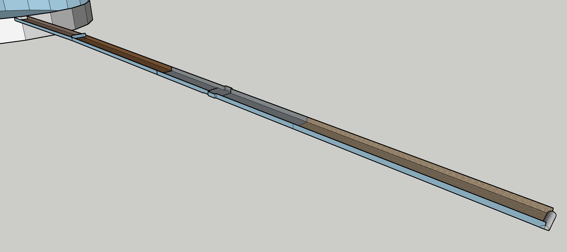
Further details of the design are shown below.
Detailed Description of the Reservoir Spillway
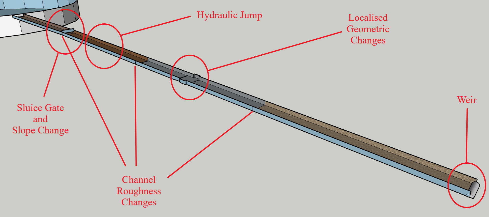
Our channel has a rectangular cross-section with width 20 m. The channel is composed of four reaches. Starting from the upstream end, the slope of each reach is 0.001, 0.002, 0.005 and 0.002 with friction factors of 0.025, 0.030, 0.030 and 0.060 respectively.
The channel emanates from a reservoir that has a water level of 6 m above the channel bed at the exit point.
At the change in slope, there is an underflow sluice gate with a contraction coefficient of 0.61. Under normal operating conditions, the gate opening is 3 m high, and the depth upstream is 8 m.
Some distance downstream of the sluice gate, the water surface rises abruptly and turbulently through a hydraulic jump, and the resulting depth is 4.4 m.
Midway through the third reach of our channel, there is an upward step of 0.03 m, followed by a width expansion of 2 m, before both the channel bed and width revert back to their original values, all within a short distance. Water typically flows at a velocity of 6.5 m/s and a depth of 3.2 m in this reach.
A weir which controls the flow sits at the downstream end of the channel, beyond which the water freely falls into the river.
Above a schematic used to design a spillway is shown. Below is an image of an actual spillway, the chute spillway of Llyn Brianne dam in Wales, as one example for a spillway in operation:
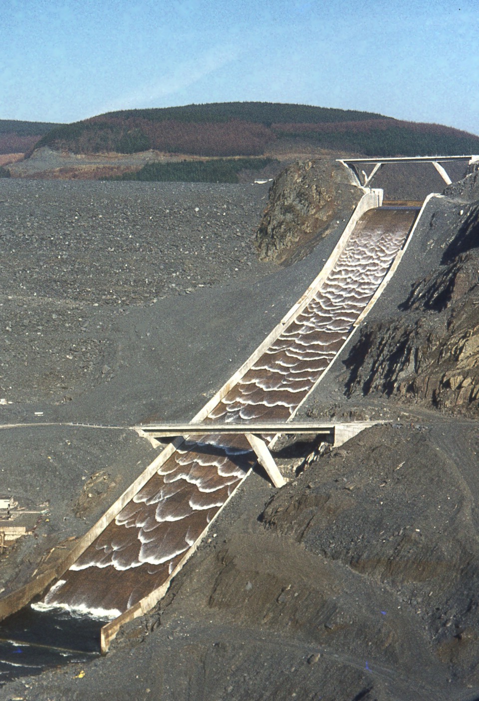
Source of the chute spillway image: By User:Velela - Own work, Public Domain, https://commons.wikimedia.org/w/index.php?curid=54055